The major types of induction motor braking include Mechanical Braking, Eddy-Current Discs, Dynamic Braking, Regenerative Braking, and Plug Braking. Mechanical braking involves creating friction between rotating and stationary components, while dynamic braking utilizes the induction motor as a generator to convert inertia into electrical energy. Regenerative braking converts mechanical energy into electrical energy and feeds it back into the power supply, and plug braking reconnects a motor to rotate in the reverse direction, providing a sudden stop. Each braking system has its applications and considerations, depending on the specific requirements of the machine.
In many installations, it is quite satisfactory to allow a machine to coast to a halt as its inertia is dissipated in friction losses within the machine. This inertia, which can be quite considerable in larger machines, can be dissipated more quickly by some form of braking. The braking system used must be of a type to suit the machine and its requirements.
The major types of induction motor braking in use are:
5. Plug Braking
Mechanical Braking
The principle of mechanical braking is to bring equipment to a complete halt and act as a parking mechanism. Generally, mechanical braking consists of creating deliberate friction between rotating and stationary components.
Machine braking systems might use more than one braking method. For example, an overhead crane might use the dynamic method for slowing down a load, and a solenoid-operated mechanical brake for holding the load stationary.
In the interests of safe working, the mechanical brake has to be fail-safe by being applied automatically when power is removed. This is a protection in the event of a power failure. Traveling cranes commonly use this form of solenoid braking on all directional movements.
In Figure 1, the brake shoes are held in the ‘on’ position against a flat pulley by a substantial spring. An application of power to the induction motor also energizes the solenoid, which releases the brake and allows the pulley to rotate.
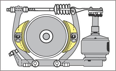
Figure 1 Mechanical braking with brake shoes and solenoid
Three-phase induction motors can be supplied by the manufacturer with a mechanically operated disc-brake as an integral part of the motor.
In Figure 2, the brake pressure is applied by means of a spring. The spring tension can be adjusted so that the braking pressure suits the particular application. The brake is released by means of a magnetic coil, which is supplied with a DC voltage by means of a rectifier in the induction motor terminal box.
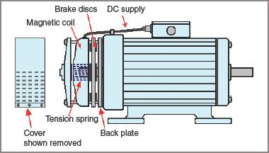
Figure 2 Typical three-phase induction motor with integral disc brake
When supply is applied to the motor terminals, it is also connected to the rectifier, and hence the brake is released. This type of brake is inherently ‘fail-safe’ because if the supply to the induction motor is interrupted at any time the brake is automatically applied.
Another system of mechanical braking uses a flat disc rotating in a mixture of finely powdered iron dust. The dust may be in a dry form or as a paste immersed in a liquid. A coil surrounds the container, and on the application of a DC voltage, the iron powder grips the disc and holds it firmly against the container. If two discs free to rotate are used the device can be used as a clutch mechanism.
It is worth noting that the mechanical system of braking usually brings the machine to a complete halt and can be used as a holding brake as well.
Eddy-Current Disc Braking
An eddy-current disc consists of a sturdy disc connected to the machine shaft and free to rotate with the machine between a set of coils held firmly in a stationary position. When a voltage is applied to the stationary coils, eddy currents are set up in the rotating disc and form a load on the machine. As the machine slows down, the induced voltages and currents become less and the rate of deceleration becomes less.
Eddy-current discs are not capable of bringing a machine to a complete stop, nor are they capable of being used as a holding brake. They simply increase the rate of slowing down of the machine.
Dynamic Braking
Dynamic braking works on the principle of using the induction motor as a generator and dissipating the machine’s inertia as electrical energy.
In AC motors, this is often achieved by disconnecting the rotating motor from the power supply and applying DC to the windings. Because the rotor is still moving, circulating currents are generated within the rotor. These form a load on the machine and slow the motor rather more quickly than just coasting to a halt.
Like the eddy-current disc method, it only hastens the slowing process and cannot bring the induction motor to a complete stop. A mechanical braking system is still needed as a holding brake.
A typical circuit is shown in Figure 3 overleaf. The main contactor and the contactor applying direct current to the stator windings are electrically interlocked and on pressing the start button the main contactor K1/5 is energized, K1.1, K1.2, and K1.3 connect the supply to the induction motor, and contact K1.5 isolates contactors K2/4 and K3/1.
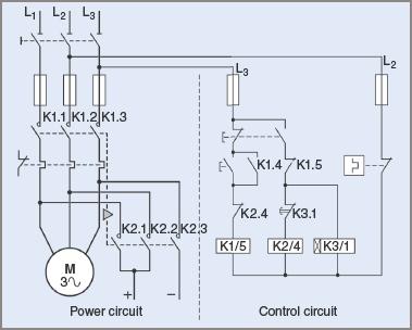
Figure 3 Braking an AC motor by DC injection (dynamic braking)
When the stop button is pressed K1/5 drops out, and the normally open section of the switch completes the circuit to contactor K2/4. When it is activated, it isolates the main contactor and simultaneously applies direct current to the stator windings. At the same time as K2/4 is energized, the time delay contactor K3/1 is also energized. After a preset time-lapse, it operates and switches off the direct current.
During the stopping process, the stop button must be held in the ‘stop’ position for a short period to activate the braking system. The direct current is usually obtained from a rectified AC supply.
A typical use for dynamic braking is in electric trains, where the driving motors are used as generators, and the energy generated is dissipated in banks of resistors. Some large cranes also use this system but, as with other applications, a system of mechanical braking is also required for bringing all movement completely to rest.
Another form of dynamic braking is by using what is known as an ‘induction generator’. Capacitors are connected across the input terminals of a three-phase induction motor. When it is necessary to stop the motor, the power supply source is removed, and resistors are connected across the motor terminals.
The induction motor, while it still rotates, generates alternating currents, which are dissipated within the resistors. The system involves extra contactors, resistors, and large capacitors, but is an excellent method for controlling the speed of motors and equipment connected to overhauling loads.
Regenerative Braking
Regenerative braking uses the inertia of a moving load to convert mechanical energy into electrical energy and feed it back into the power supply source. This method is not used very often with AC sources; it is a more involved method than those described above and involves the use of extra equipment.
The electrical energy fed back into the supply source has to be considerable to justify the additional expense. It follows that the mechanical energy available to supply it also has to be considerable.
A typical application of regenerative braking is its use in electric traction systems such as trains or trams. There are often thousands of tones on the move, and this constitutes considerable inertia. If this energy can be transformed into electrical energy and slow down the train or tram, a large saving in electricity costs can be achieved. There will also be a saving in wear and tear on the brake shoes used in a mechanical system.
The system becomes less effective as the vehicle slows, and mechanical braking is also required. At some point, the electrical energy being generated will be insufficient to be fed back into the supply line and the system has to be disconnected from the supply. On occasion, the system may then use dynamic braking as a further slowing process.
Because of the expense of fitting extra equipment to machines, plus the fact that the method cannot completely stop and hold machinery in a stationary position, the applications of regenerative braking are limited. For AC working, its main use is in controlling overhauling loads, for example, cranes lowering heavy loads.
Plug Braking
Plug braking with three-phase induction motors is the system of reconnecting a motor to rotate in the reverse direction while still rotating in the forward direction. It is a sudden and almost violent method for bringing a motor to a complete stop. The actual time taken depends on the amount of inertia in the accompanying machine.
In order to use plugging as a stopping mechanism, some means must be provided to remove all power from the motor at the instant of change in direction. This can be done with a friction-operated single-pole changeover switch mounted on the induction motor driving shaft. Another method uses an eddy-current disc rotating between magnets to activate contacts, which in turn control the main contactors.
The starter circuit has push-buttons to activate rotation in the required direction, and the movement of the shaft closes the appropriate contact and allows the main contactor for that direction to energize.
A stop button allows the contactor in use to drop out and also activates the contactor for the opposite direction. This is latched in until the first amount of reverse movement occurs. This movement opens the holding-in contact of the starter and removes all power from the motor.
A circuit for a three-phase induction motor using the plugging method of braking is shown in Figure 4.
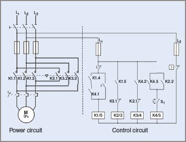
Figure 4 Typical diagram for plug braking of an AC motor
The operation of the circuit is as follows.
1. Pressing the start button energizes K1/5 via the stop button and the TOL contact. K1.1, K1.2, and K1.3 close and connect the supply to the induction motor so it runs in the normal direction. K1.5 energizes K2/2.
2. K2.1 opens and prevents K3/4 from energizing. K2.2 closes and energizes K4/3 via the now-closed shaft rotation switch S1. Note that S1 opens whenever the shaft is stationary.
3. K4.1 and K1.4 close and bridge out the start button so that upon release of the button K1/5 remains energized.
4. When the stop button is pressed, K1/5 drops out and K1.5 opens and de-energies K2/2. Contact K2.1 now closes, and as K4/3 is still energized via S1, K3/4 energizes and connects the supply to the motor in the reverse direction. When the shaft stops rotating, switch S1 opens and K4/3 and K3/4 both drop out.
Motors generally have to be specially designed for this application by having stronger driving shafts. The drive shaft has to withstand the forces created by the driven machine’s inertia in bringing the machine to a halt.
The rotor bars also have extra mechanical forces exerted on them. Again, if it is necessary, some mechanical brake may have to be applied to hold the machine in position. One plugging stop is generally recognized as being equivalent to about three repetitive normal starts.
The induction motor windings might also have to be specially designed if the application calls for repeated starting and stopping. It is characteristic of a three-phase induction motor that the amount of current flowing when plugging is applied is almost equal to the normal starting current. Also, the starting current flow is applied for almost the same length of time as normal starting.
Probably the most common application is in larger production lathes doing repetition process work. In such an application, a mechanical holding brake might not be needed.
Electronic starters equipped with current limiting or ramping circuits can use this system of braking with some success. The inverter circuits can sometimes be reversed in action and the excess generated energy converted to direct current and dissipated by dynamic braking. Normally it cannot be fed back into the supply source as can be done with a normal regenerative braking system.
Induction Motor Braking Key Takeaways
The various braking methods for induction motor starter systems—namely Mechanical Braking, Eddy-Current Disc Braking, Dynamic Braking, Regenerative Braking, and Plug Braking—play crucial roles in enhancing motor control and operational safety. Each method offers specific advantages tailored to different industrial applications, such as cranes, electric trains, and heavy machinery. By selecting the appropriate braking technique, engineers can ensure efficient energy use, minimize wear and tear, and meet operational safety standards.