The article covers electrical fault finding in control circuits, emphasizing the need for common sense, awareness, and logical approaches to diagnose faults in electrical systems. It discusses various causes of faults, symptoms, and potential sources, highlighting the importance of observation, communication, and systematic testing techniques to identify and rectify issues efficiently. Additionally, it provides insights into the application of specific testing equipment and safety measures essential for effective fault diagnosis and resolution in electrical control circuits.
Discovering and diagnosing faults successfully requires common sense, awareness, and knowledge of how the equipment operates, as well as applying a logical approach to analyzing faults and checking and testing techniques. Practical communication skills and good workplace relationships are also helpful as they foster information sharing and cooperation.
The leading cause or causes of faults will usually be one or a combination of the following:
- Equipment design faults—production tasks may be outside the equipment’s regular operation specifications, for example, if purchased from overseas or modified. Specific functions can result in unexpected production stops.
- Wiring and equipment faults—electrical and/or mechanical damage due to work environment, wear and tear, sensor or detector adjustments, predictive-preventative programmed maintenance, and repair ‘windows of opportunity’ and schedules.
- Operator error—lack of training or support, set-up mistakes, fatigue, stress, emergency stop operation, blocked and misaligned sensors or detectors.
Fault finding is a significant part of electrical work and is a skill that requires knowledge of the circuit operation through:
- familiarity with equipment operation and control under regular operation
- observation of equipment operation and the sequence that led to the fault condition
- careful study of the circuit schematics and wiring diagrams.
Plant maintenance and breakdown staff will develop this knowledge through experience over time. The number of recurring faults in production environments can be high. Staff may have to deal with anything from straightforward machine stoppages or process-sequence resets to minor sensors and detectors adjustments to more significant fault repairs. After three and six months on the job and under the guidance of experienced mentors, technical specialists (including plant electricians) can diagnose and carry out arguably 80% of the required fault rectification, repair, and maintenance tasks.
Knowing how to operate, understand, and repair equipment enables electricians and technicians to become technical ‘gun’ operators.
Symptoms, Faults, and Causes
As the in-house electrician, you are advised that one of the equipment plant conveyor systems has suddenly stopped and will not restart. This is a symptom of a fault condition, and the cause could be mechanical, electrical, or operator-related. The state of the equipment illustrates the importance of an electrician/technician being able to quickly identify and discern between symptoms, fault conditions, and causes.
The cause of equipment stopping suddenly and then not being able to be restarted could be loss of supply, circuit-breaker or overload trip, an operator forgetting to reset the emergency stop pushbutton, or a mechanical jam—there are multiple possibilities. When determining the fault, its cause also needs to be found. For example, was an overload trip due to the motor drawing excessive current because of a jam or a dropped phase? And what was the root cause of the jam or the dropped phase?
If you are not familiar with the equipment and its operation, or you do not have enough information about the fault that has been reported, listen carefully to the operator’s description of what happened and then ask questions. (In cases where the equipment is still functioning, observe its status closely during operation or when the fault recurs.)
The types of questions that you could ask the operator are:
- What happened?
- What was the equipment/machine doing when the fault occurred?
- How does it work normally?
The operator’s responses can provide helpful information. You can also increase your awareness of the situation by doing the following:
- Looking—for something obvious, such as smoke, sparks, blown fuses, overloads, broken mechanical parts or brackets, misaligned sensors, mechanical jamming of moving parts, broken cables or exposed, overheating or burnt wiring, coils or components.
- Listening—for mechanical noises such as clunking, grinding, or scraping metal; noisy bearings, laboring motors, humming, buzzing, and chattering of relays or contactors.
- Smelling—a smell of plastic or rubber may indicate overheating cables; a smell of varnish could indicate burnt-out or overheated coils, contactors, transformer windings, or motors.
- Touching—check motors for excessive vibration or overheating (while, of course, avoiding burnt hands and electric shocks).
Taking these steps can rule out many simple faults and help determine whether there is power present. If you find something at fault, damaged, or out of adjustment, follow the necessary equipment shutdown, isolate, lock-out, and tag-out procedures.
Applying a logical process of elimination and checking allows faults to be more readily identified and rectified. Following adjustment, replacement, or repair, check the rest of the circuit. There may be other fault causes that need to be identified and corrected. Damaged electrical components—particularly circuit cards—could be damaged further (or even fail) when the circuit is re-energized.
Checking and Testing Techniques and Procedures
If the procedures outlined in the Workplace Scenario do not establish the fault and its cause, two steps may need to be taken. One is to follow a fault escalation procedure (many production and processing environments have them). This procedure should state which staff should be notified and when, as well as fault-finding processes and time frames.
The second step is to follow fault-finding processes for electrical equipment. Depending on the fault condition and the equipment, this can involve one of the following approaches:
Systemic—live testing for voltage (see Figure 1) or dead testing for continuity (Figure 2), using a multimeter or similar function-testing device. This approach involves one probe lead of the meter being attached to the circuit neutral. The other test probe is moved along the circuit path, checking each component or device in series to determine the fault.
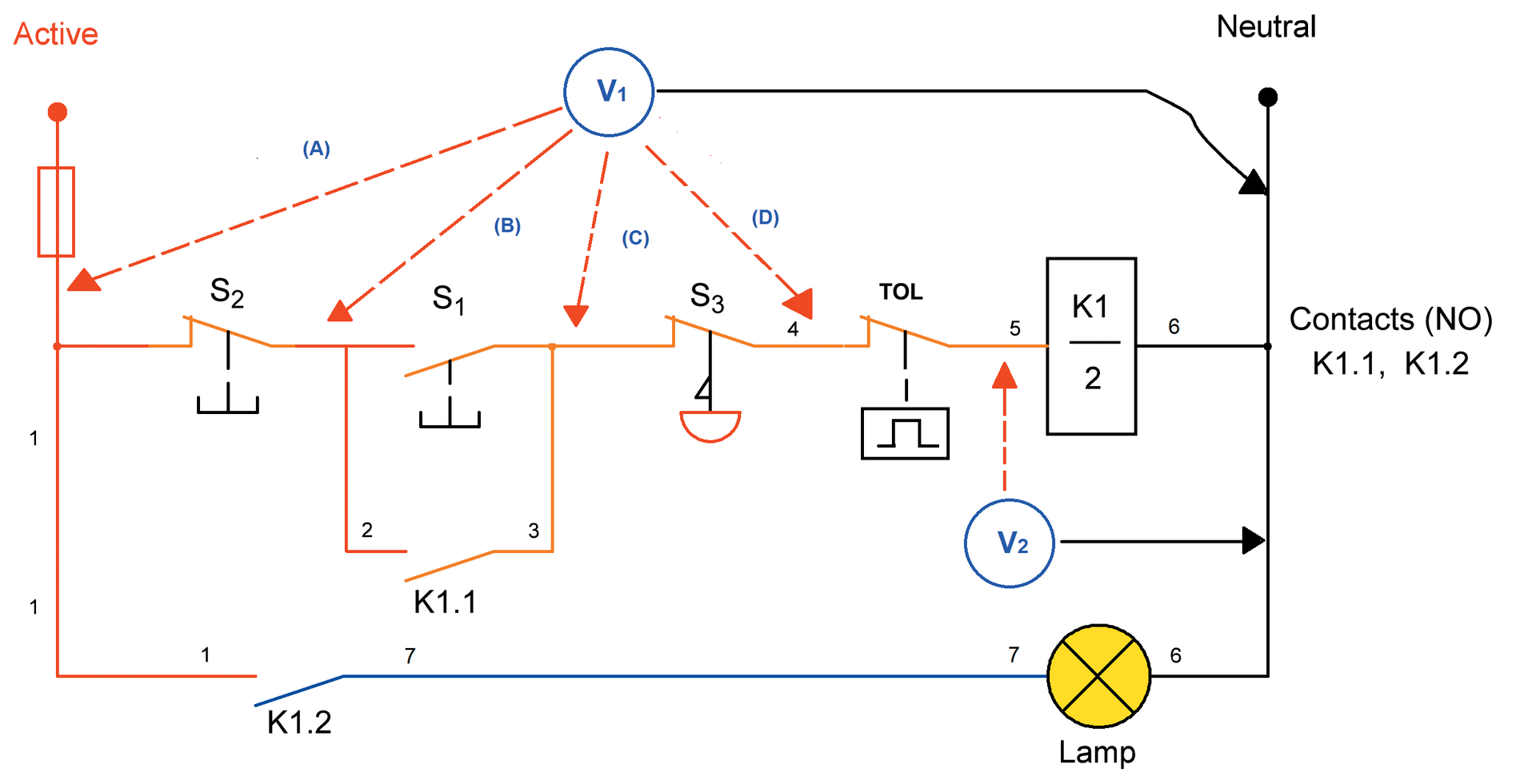
Figure 1. Live testing of control circuits using a multimeter.
Circuit division—dead testing (for continuity) or live testing (for voltage) by dividing the circuit in half. This is particularly common in emergency stop loops to determine an emergency stop operation and its location.
A multimeter can be used to determine circuit path continuity, as shown in Figure 2. As the circuit is de-energized (or ‘dead’), it is possible to check from the contactor coil through to the active supply rail. By pressing the S1 start pushbutton, the circuit path is established (continuity) without needing supply.
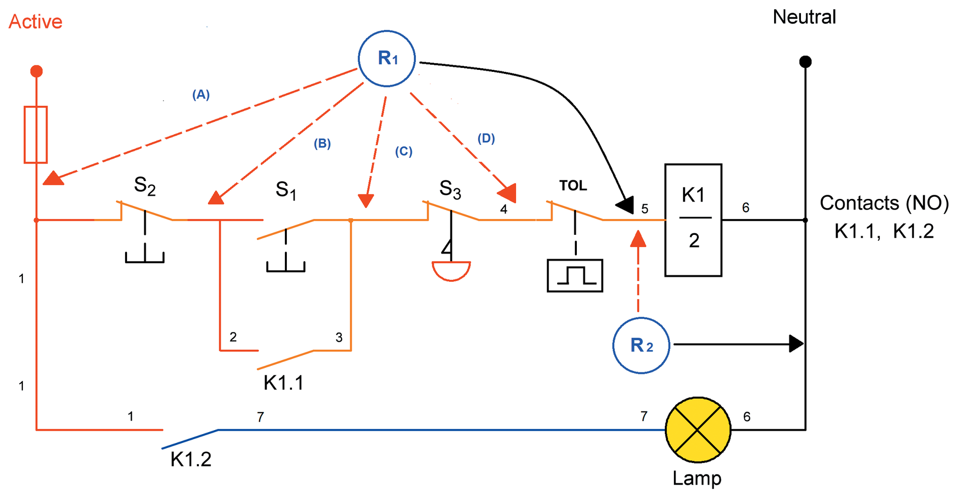
Figure 2. Dead testing a de-energized circuit.
Applying Circuit-Checking and Testing Techniques to an Electrical Control Circuit
It is a requirement of electrical work that the safe and correct operation of powered plants and equipment is ensured. The correct type of test equipment can, if used correctly, prevent unwanted and ‘false’ equipment sequence start-up. (Circuit and voltage testers with inherent capacitance as part of their design should not be used for this.) Common test equipment includes:
- Voltage testers—usually high-impedance multimeters on the voltage range, although test lamps (low impedance) that are fused and insulated may be used in some situations.
- Ohmmeter—for checking circuit continuity and resistance of circuit components. They are used for open circuits, zero resistance for switch operation, open and closed contacts, conductors, and terminal connections. They provide relay coil and element resistance readings.
- Clamp meter—‘tong tester’ for non-contact testing of current, unbalanced three-phase loads and current-leakage situations. Modern clamp meters include voltage and resistance capability using test probes.
- Insulation resistance (IR) meters—for testing insulation integrity of conductors, and testing between phase windings of motors. Some IR testers incorporate resistance and continuity functions.
It is advantageous to use dedicated test equipment. While a general-use multimeter can measure voltage, current, resistance, and continuity, selecting the wrong setting can damage the equipment under test.
Live testing by inexperienced electrotechnology workers can be dangerous and can lead to an electric shock situation and/or equipment damage. Before attempting any testing, assess the situation, use common sense, and follow safe work practices and procedures. It is helpful to keep the following in mind:
- Are you trained, qualified, and authorized to carry out testing?
- Does the workplace have organizational policies and procedures for working on machinery and equipment/live equipment? Do you know what they are?
- Do you have the appropriate personal protective equipment, tools, and test equipment to perform the work?
- Have you checked and tested your tools and equipment for damage, safe use, and correct operation?
- Are you familiar with the equipment, do you have a basic understanding or working knowledge of it and can you perform work following manufacturer recommendations?
- Do you have the required wiring schematic drawings and manuals?
- Do you need to deploy a rescue kit and have an observer?
- Have you conducted a risk assessment?
Appropriate in-house and manufacturer equipment training is usually provided to qualified, authorized on-site staff. However, if you are engaged as an outside contractor, the questions above must be addressed. Mistakes can damage equipment, cause lost production, and cause downtime while sourcing replacement components and spare parts.
Fault Finding Control Circuits Key Takeaways
Understanding and effectively diagnosing faults in control circuits are crucial for ensuring electrical systems’ safe and efficient operation in various applications. Whether in industrial settings, commercial facilities, or residential environments, identifying and rectifying faults promptly can prevent costly downtime, equipment damage, and potential safety hazards. By employing systematic fault-finding techniques, utilizing appropriate testing equipment, and adhering to safety protocols, electricians and technicians can maintain optimal performance, minimize disruptions, and enhance overall reliability in electrical control circuits.