The article provides an overview of power electronic devices and circuits, including power semiconductors such as diodes, thyristors, power BJTs, insulated-gate bipolar transistors, and static induction transistors. It also discusses power electronic circuits like voltage regulators, diode rectifiers, power amplifiers, switches, controlled rectifiers, AC voltage controllers, choppers, and inverters, highlighting their functions and applications.
Power semiconductors can be classified into five groups:
- Power diodes.
- Thyristors.
- Power bipolar junction transistors.
- Insulated-gate bipolar transistors.
- Static induction transistors.
Figure 1 depicts the symbols for common power electronic devices.
| Device | Device symbol |
|---|---|
| Diode | 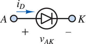 |
| Thyristor |  |
| Gate turnoff thyristor (GTO) |  |
| Triac |  |
| NPN BJT |  |
| IGBT | 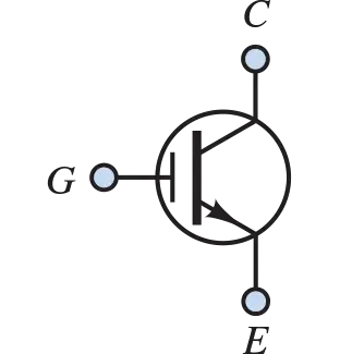 |
| n-channel MOSFET | 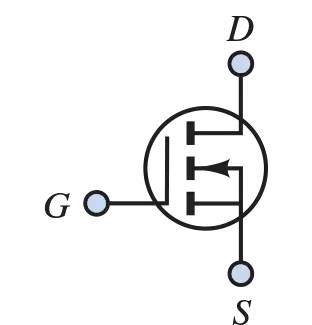 |
Figure 1. Classification of power electronic devices
Power Diodes
Power diodes are functionally identical to small-signal diodes except for their ability to manage much larger voltages and currents. For example, a general-purpose diode may be rated at 3 kV and 3.5 kA, while a high-speed diode may be rated as high as 3 kV and 1 kA.
Schottky diodes are even faster, with switching intervals in the nanosecond range, but they are typically limited to 0.1 kV and 0.3 kA. The forward voltage drops of small-signal and power diodes are similar, both being on the order of 1 V, which is usually negligible compared to the voltages found in power applications. As a result, power diodes often approximate ideal switches.
Thyristors
Thyristors are one of the oldest power electronic devices and are similar to power diodes except for an additional gate terminal that determines when conduction begins. A small current injected into the gate will trigger conduction if the diode portion of the thyristor is forward-biased, as indicated in Figure 1. Once triggered, the gate current is not needed to maintain conduction, which continues until the diode portion of the thyristor is reverse-biased. Thyristors can be rated at up to 6 kV and 3.5 kA. The turnoff time of a thyristor is an important characteristic and can be as short as 10 µs; however, a short turnoff time is usually accompanied by a lower power rating.
Over the years, many varieties of thyristors have been developed, including the gate turnoff (GTO), reverse-conducting (RCT), static induction (SIT), gate-assisted turnoff (GATT), MOS controlled (MCT), and force- and line-commutated thyristors, as well as the original silicon-controlled rectifier (SCR) and light-activated SCR (LASCR). The operation of each of these devices is a slight modification of the basic thyristor. Of this group, only the GTO can be turned on and off without the aid of a separate commutation circuit. A short negative pulse to the gate turns off a GTO.
A triac is essentially a pair of oppositely directed thyristors connected in parallel, as shown in Figure 1. A single gate enables conduction in either direction. Conduction is maintained until the thyristor is no longer forward-biased in either direction.
Power BJTs
Power BJTs can reach ratings up to 1,200 V and 400 A, and they operate in much the same way as a conventional BJT. Power BJTs are used in power converter applications at frequencies up to around 10 kHz. Power MOSFETs can operate at somewhat higher frequencies (a few to several tens of kilohertz) but are limited in power (typically up to 1,000 V and 50 A). Insulated-gate bipolar transistors (IGBTs) are voltage-controlled (because of their insulated gate, reminiscent of insulated-gate FETs) power transistors that offer superior speed with respect to BJTs but are not quite as fast as power MOSFETs.
Power Electronic Circuits
One possible classification of power electronic circuits is given in Table 1.
Table 1. Power electronic circuits
| Circuit | Function |
|---|---|
| Voltage regulator | Regulate the output of a DC voltage supply |
| Diode rectifier | Convert fixed AC voltage to fixed DC voltage (single- or multi-phase) |
| Power amplifier | Amplify large-signal voltages and currents |
| Switch | Connect/disconnect one part of a circuit to/from another |
| Controlled rectifier | Convert fixed AC voltage to variable DC voltage (single- or multi-phase) |
| AC voltage controller | Convert fixed AC voltage to variable AC voltage (single- or multi-phase) |
| Chopper | Convert fixed DC voltage to variable DC voltage |
| Inverter | Convert fixed DC voltage to variable AC voltage (single- or multi-phase) |
The last four circuits listed in Table 1 are all generally known as converters, and their principal shared characteristic is the use of a switch to control or vary their output. For example, the DC output of a thyristor-based controlled rectifier is variable in the sense that the gate current can be varied to control the initiation of conduction, resulting in a DC output like that illustrated in Figure 2. The firing angles α and α + π indicate the initiation of conduction through thyristors T1 and T2 during each period of the AC supply. This type of AC-DC converter is commonly used in DC motor applications.
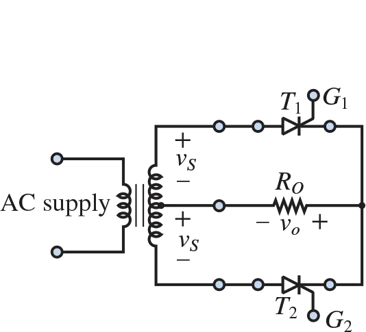
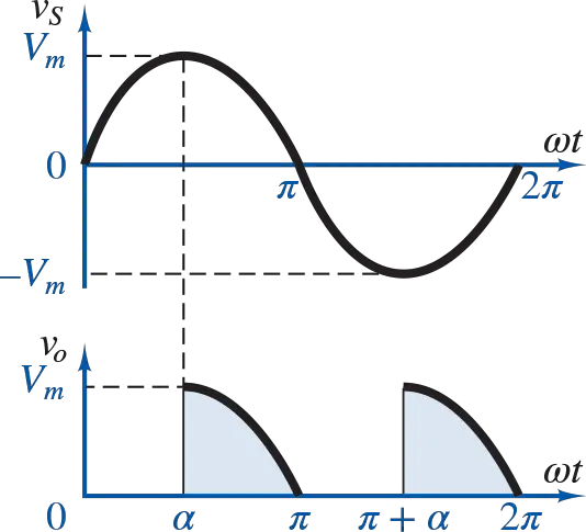
Figure 2. AC-DC converter circuit and waveform
As another example, Figure 3 shows one type of AC voltage controller, where the bidirectional capability of a triac is employed to modify an AC waveform. The period of the output waveform matches that of the input waveform; however, the rms value of the output vo is smaller than that of the input vs. This type of circuit is known more generally as an AC-AC converter.
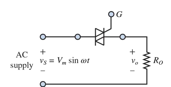
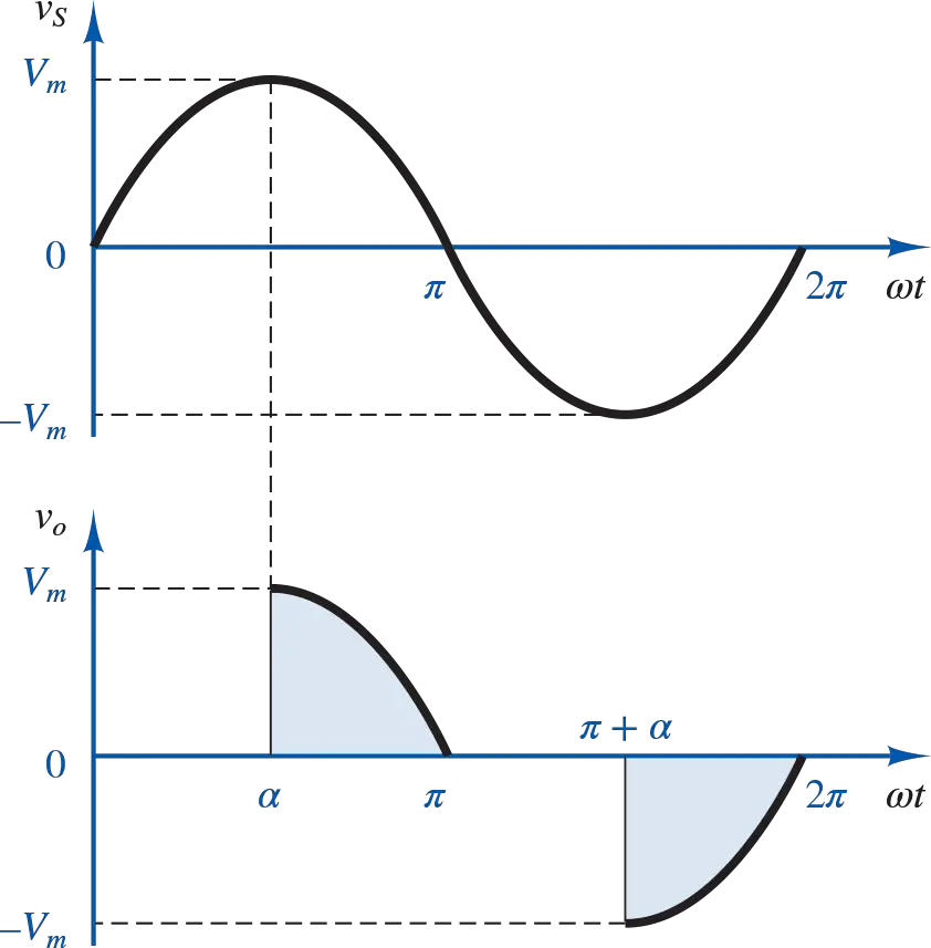
Figure 3. AC-AC converter circuit and waveform
Figure 4 shows a basic chopper, or switching regulator, converts a fixed DC source to a variable DC source. In this circuit, a BJT is employed as a switch to enable/disable conduction according to the duty cycle of the base-emitter voltage. The reduced DC average of the output waveform is determined by that duty cycle. Such DC-DC converters are often used as variable-voltage supplies for DC motors.
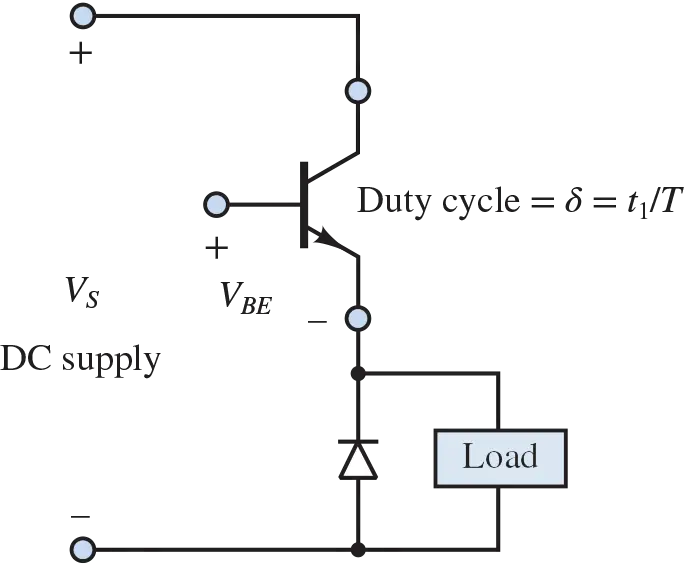
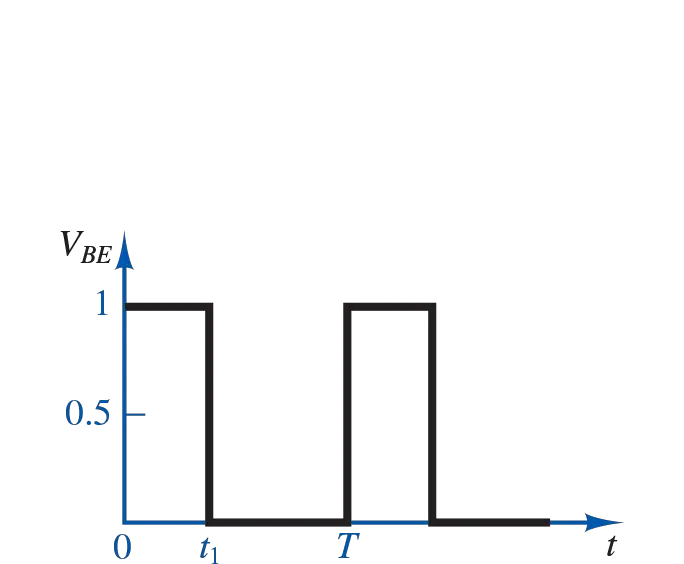

Figure 4. DC-DC converter circuit and waveform
Figure 5 shows a basic inverter, which converts a fixed DC supply to a variable AC supply by coordinating the switching of pairs of transistors. Such DC-AC converters find application in AC motor control.
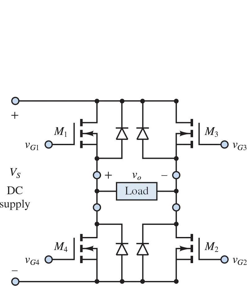
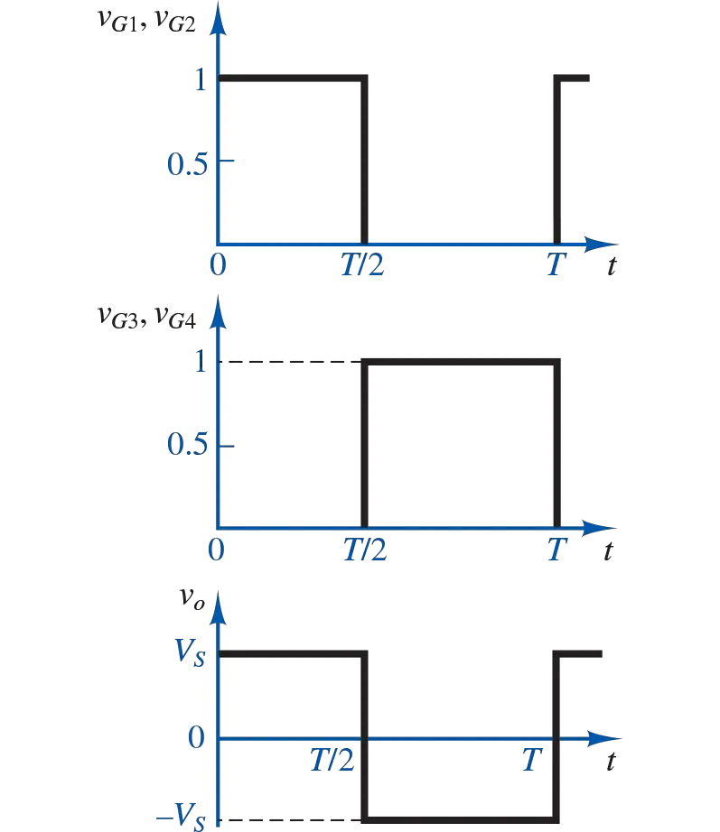
Figure 5. DC-AC converter circuit and waveform
Key Takeaways
From power diodes to complex power electronic circuits like inverters and voltage regulators, each component plays a crucial role in various industries and applications. Understanding these devices and circuits is essential for engineers and professionals working in power electronics, enabling them to design, implement, and optimize systems for a wide range of purposes, from motor control to renewable energy integration. As technology continues to evolve, the field of power electronics remains dynamic, driving innovations that enhance efficiency, reliability, and performance across numerous sectors.