The programmable unijunction transistor is a device that overcomes the major disadvantages of the UJT. This article covers construction, basic operation, and characteristics of Programmable Unijunction Transistor.
Programmable UJT (PUT) Construction
The PUT is a three-terminal four-layer device like the SCR, the difference being that the gate terminal is connected to the n-type layer near the anode.
The PUT is not manufactured in the same high current and voltage ratings as the SCR. It is usually only available in smaller packages, similar to the very low current (1.0 A) SCRs. The structure and the symbol are shown in Figure 1.
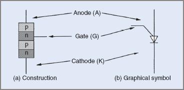
Figure 1 PUT construction and symbol
Programmable UJT (PUT) Operation
A PUT is similar to a small SCR and operates in the same manner. It will block current until triggered on. When triggered it will latch on if the current is high enough and remain on until the anode current falls below the holding current.
To trigger the PUT into the on state, current is passed from the anode to the gate, therefore the anode–gate junction must be forward biased and the anode potential 0.6 V higher than the gate. The biasing and current directions in the PUT are shown in Figure 2.
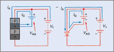
Figure 2 PUT biasing and current flow
A feature of the PUT when compared with the UJT is that the on resistance is much lower and can carry much higher peak values of current. It can therefore provide higher levels of trigger energy.
Programmable UJT (PUT) Characteristics
The PUT characteristics are similar to those of the UJT, the major differences being that the reverse leakage current (gate to anode) is much lower, and the on resistance is much lower. The PUT characteristics are shown in Figure 3.

Figure 3 PUT anode characteristics curve
The transition from the off to the on state is also faster in the PUT than in the UJT.
The most significant advantage of the PUT over the UJT is that the standoff ratio is variable, externally programmable and not determined by the structure or manufacture of the device. The peak point voltage may be varied by varying the potential on the gate of the PUT relative to the anode.
Programmable UJT (PUT) Relaxation Oscillator
The PUT is used in a relaxation oscillator circuit similarly to the UJT. The distinction is that the standoff ratio is programmable. Note that the PUT oscillator also employs an RC timing circuit like the UJT oscillator. The PUT oscillator circuit is shown in Figure 4.
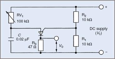
Figure 4 PUT relaxation oscillator
The resistors R1 and R2 are called the ‘programming resistors’. It is these resistors that set the potential on the gate relative to the anode.
Programmable Unijunction Transistor Oscillator Operation
The PUT oscillator operates in a similar manner to the UJT oscillator. Its operation may be summarized as follows:
- Resistors R1 and R2 set up a bias voltage on the gate terminal of the PUT. The voltage is dependent on the supply voltage and the respective values of R1 and R2. These resistors program the standoff ratio.
- When the supply is connected, the capacitor charges via RV1. The rate at which it charges is fixed by the time constant of the RC circuit.
- When the anode voltage (the voltage across the capacitor) reaches a value 0.6 V above the gate voltage, the PUT turns on and latches on.
- When the PUT turns on, the capacitor discharges via the PUT and R3. The resistance of this discharge path is very low, so the discharge time is very short.
- The resulting output pulse will have a high peak value with a very fast rise time, ideal for triggering an SCR or a triac.
- The oscillator relaxes back to the off state when the capacitor is discharged and the cycle recommences.
As discussed in PUT Characteristics section, the voltage at the gate is fixed by the voltage divider and the voltage at the anode required to turn the PUT on is 0.6 V higher than this voltage. The anode voltage required to turn the PUT on is the peak point voltage VP. This value is determined from:
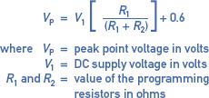
$$V_{P}=V_{1}\left [ \frac{R_{1}}{\left ( R_{1}+R_{2} \right )} \right ]+0.6$$
$$\textrm{where }V_{P}=\textrm{peak point voltage in volts}$$
$$V_{1}=\textrm{DC supply voltage in volts}$$
$$R_{1}\textrm{ and }R_{2}=\textrm{value of the programming resistors in ohms}$$
It is not essential that the values of the programming resistors be expressed in ohms. What is essential is that both values must be in the same units: Ω, kΩ or MΩ.
This is similar to the expression used for the UJT, the difference being that in the case of the PUT, the standoff ratio is determined by the value of the external divider resistors. The PUT is therefore said to have a programmable standoff ratio—programmed by external resistors. The standoff ratio may therefore be any value between 0 and 1.0. This is a significant advantage when compared with the UJT oscillator.
Example 1
Assume that the supply voltage in the circuit in Figure 4 is 20.0 V. Determine the standoff ratio and the peak point voltage.
$$\textrm{Standoff ratio }\eta =R_{1}/\left ( R_{1}+R_{2} \right )=10.0/\left ( 10.0+10.0 \right )=0.5$$
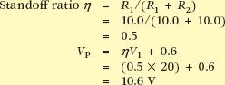
$$V_{P}=\eta V_{1}+0.6=\left ( 0.5\times 20 \right )+0.6=10.6V$$
Assume that the programming resistors in Figure 4 are changed to R1= 6.8 kΩ and R2 = 12.0 kΩ. Determine the standoff ratio and the peak point voltage.
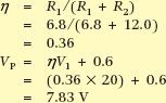
$$\eta =R_{1}/\left ( R_{1}+R_{2} \right )=6.8/\left ( 6.8+12.0 \right )=0.36$$
$$V_{P}=\eta V_{1}+0.6=\left ( 0.36\times 20 \right )+0.6=7.83V$$
Example 1 illustrates that the peak point voltage can be altered without changing the actual trigger device or the supply voltage.
The waveforms produced by the PUT relaxation oscillator are shown in Figure 5 overleaf. Note the similarity to the UJT oscillator waveforms.
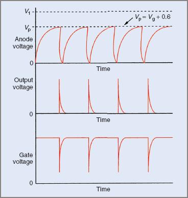
Figure 5 PUT oscillator waveform
Both oscillator circuits examined so far have been connected to a pure DC supply and the frequency of the pulses, or the time delay after the commencement of a cycle, was varied. Where the thyristor is connected to an AC supply, the trigger pulses must be synchronized with the supply. The time delay after the start of a cycle is important and should be the same for each cycle or half-cycle.
A feature of both UJT and PUT oscillator circuits is that they only produce output pulses of one polarity. In the case where a triac is to be triggered, pulses of alternate polarities may be better suited and an alternative device and trigger circuit is required.
Programmable Unijunction Transistor Key Takeaways
The Programmable Unijunction Transistor (PUT) presents a significant improvement over the conventional UJT, offering flexibility through its programmable standoff ratio and faster switching characteristics. These attributes make PUTs highly valuable in applications where precise timing and reliable triggering are essential—such as in relaxation oscillators, pulse generation circuits, and the controlled firing of SCRs and triacs. The ability to externally adjust key operating parameters without altering the device itself enhances design versatility, making PUTs ideal for use in timing, waveform shaping, and synchronization tasks in both analog and digital circuits.