The article provides an overview of the Unijunction Transistor (UJT), including its construction, operation, and key characteristics, particularly its role as a triggering device for thyristor power-control applications. It also explains the working of a UJT-based relaxation oscillator, its components, timing behavior, and limitations.
Thyristor power-control devices must be accompanied by a circuit that provides pulses of current to the gate terminal to cause the thyristors to turn on.
The UJT is one of the more common trigger devices used in conjunction with thyristor power-control devices.
Unijunction Transistor Construction
The UJT is the simplest of all the trigger devices. It is a three-terminal silicon device with only one semiconductor junction, hence the term ‘unijunction’.
The UJT consists of a lightly doped n-type wafer of semiconductor material known as the ‘channel’. A small current flow is established in this channel to set up internal voltage drops that are the key to the operation of the UJT.
Diffused into the channel is a heavily doped p-type region known as the ‘emitter’. It provides the current carriers for the current pulse produced by a UJT. The construction and graphical symbol are shown in Figure 1.
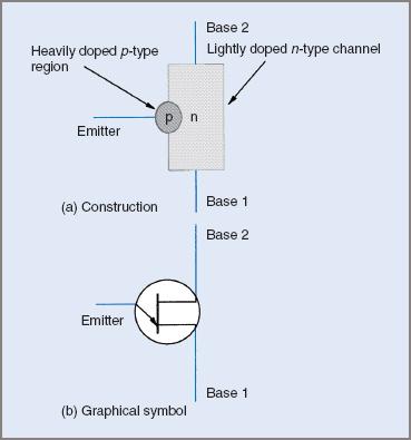
Figure 1 UJT construction and symbol
The UJT is used extensively as a triggering device for thyristors.
Unijunction Transistor Operation
A simple way to examine the operation of the UJT is to consider it to be a voltage divider and a p–n diode. The manner in which the device is manufactured is such that the interbase resistance, that is, the resistance between base 1 and base 2, is high. This value will be in the range 5 to 10 kΩ. The interbase current will therefore be very low, only a few milliamps. This current establishes a voltage drop across the internal resistance of the device (rB1 and rB2).
The relative values of rB1 and rB2 are dependent on the physical location of the emitter region in relation to the ends of the channel. The polarity of these voltage drops is shown in Figure 2.
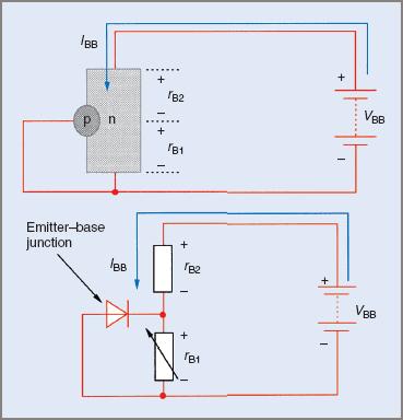
Figure 2 UJT internal voltage drops diagram
The relative values of the voltage drops in the UJT are dependent on the relative values of the internal resistances. The ratio of rB1 to the total interbase resistance (rB1 + rB2) will fix the value of the voltage at the cathode terminal of the emitter base junction.
This voltage will be between 0.5 and 0.85 of the base-to-base voltage (VBB). The ratio of rB1 to (rB1 + rB2) is known as the ‘intrinsic standoff ratio’ (η). This value is fixed at manufacture and cannot be altered.
Under the bias conditions specified above, a very small leakage current flows out of the emitter terminal and returns to the negative of the supply. This current is very small and is usually ignored.
If a supply is connected to bias the emitter with respect to base 1, this leakage current will decrease as the emitter base voltage increases. When the emitter base voltage is equal to the internal voltage drop across rB1 the emitter current will be zero.
As the emitter voltage becomes more positive, the emitter becomes forward biased. When the emitter voltage is 0.5 V greater than VrB1, the emitter conducts heavily. This results in very large numbers of current carriers being injected into the channel.
The resistance of the channel (rB1) decreases rapidly to a value that may be as low as a few hundred ohms. The emitter voltage at which this conduction takes place is termed the ‘peak point voltage’ (Vp).
The current flow under this set of conditions is shown in Figure 3 overleaf.

Figure 3 UJT emitter current configuration circuit diagram
The peak point voltage will be determined by the supply voltage (VBB) and the standoff ratio (η).
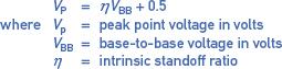
$$V_{P}=\eta V_{BB}+0.5$$
$$\textrm{where } V_{P}=\textrm{peak point voltage in volts}$$
$$V_{BB} =\textrm{base-to-base voltage in volts}$$
$$\eta =\textrm{intrinsic standoff ratio }$$
Example 1
Assume that the UJT in Figure 3 has a standoff ratio of 0.65 and the supply voltage is 20.0 V. Determine the peak point voltage for the UJT.
![]()
$$V_{P}=\eta V_{BB}+0.5=\left ( 0.65\times 20 \right )+0.5=13.5V$$
It is important to remember that the standoff ratio is fixed and that the peak point voltage is determined by the supply voltage. If a different peak point voltage is required, the supply voltage may be altered or a UJT with a different standoff ratio substituted.
Unijunction Transistor Characteristics
The characteristics of the UJT make it ideal for use in a circuit intended to trigger thyristor power-control devices. If the UJT is used in conjunction with an RC timing circuit it will produce an output that consists of short duration pulses with a very fast rise time, ideal for the triggering of SCRs, GTO thyristors and triacs.
From the emitter characteristic (V–I) curve shown in Figure 4 it can be seen that the resistance of the UJT (emitter to base B1) decreases significantly once the peak point voltage is reached. The decrease occurs quite rapidly.
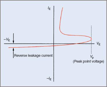
Figure 4 UJT emitter characteristics curve
UJT Relaxation Oscillator
The circuit shown in Figure 5 is applicable to low-level power-control applications with SCRs and triacs. The only modification to the circuit may be to use a pulse transformer.
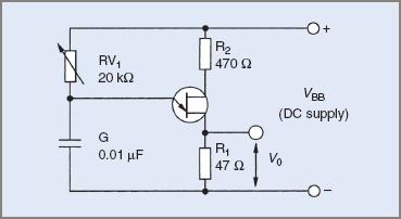
Figure 5 UJT relaxation oscillator circuit diagram
The circuit consists of the UJT and an RC timing circuit. When the supply to the timing circuit is first turned on, the voltage across the capacitor will increase at a rate determined by the values of the resistor and the capacitor.
The time taken for the capacitor voltage to reach 63 per cent of the supply voltage is referred to as the time constant (τ) of the circuit. The time may be modified by varying either the value of the resistor or the value of the capacitor. In practice it is found that it is easier to alter the value of the resistor.
UJT Relaxation Oscillator Operation
The operation of a UJT relaxation oscillator is straightforward and may be summarized as follows:
- When the supply is first turned on, the capacitor charges via the variable resistor RV1 at a rate deter-mined by the setting of the resistor and the size of the capacitor.
- When the capacitor voltage is equal to the peak point voltage, the emitter conducts. The emitter will conduct heavily, with the internal resistance of the UJT falling to a very low value.
- When the emitter conducts, the capacitor will discharge through the UJT and R1. The resistance of the discharge path is much lower than that of the charging path, so the capacitor will discharge much more quickly than it charges.
- The resulting current through R1 develops the output voltage pulse required to trigger an SCR or a triac. Since the discharge time for the capacitor is very short, the current will have a relatively high peak value and a fast rise time.
- Altering the value of RV1 will only change the time it takes for the capacitor to charge to the peak point voltage. It does not alter the peak point voltage. Altering the time constant of the circuit will alter the frequency of the output pulses from the oscillator.
- When the capacitor has discharged, the UJT will relax back to the off state, hence the name relaxation oscillator. The cycle then recommences.
Example 2
If VBB is equal to 15 V in the circuit in Figure 5, and the standoff ratio is 0.63, determine the peak point voltage.
![]()
$$V_{P}=\eta V_{BB}+0.5=\left ( 0.63\times 15 \right )+0.5=9.95V$$
The frequency of the pulses from this circuit will depend on the time constant. The actual calculation of frequency can be complex but if the standoff ratio is equal to, or near, 0.63, the frequency may be determined from a simplified expression:
$$f=\frac{1}{RC}$$
$$\textrm{where f}=\textrm{output frequency in hertz}$$
$$R=\textrm{circuit resistance in ohms }$$
$$C=\textrm{circuit capacitance in farads }$$
Example 3
In the circuit in Figure 5, determine the output frequency if the standoff ratio is 0.63, the value of RV1 is 10 kΩ and the capacitance is 0.1 μF.
$$f=\frac{1}{RC}=\frac{1}{10\times 10^{3}\times 0.1\times 10^{-6}}=1000Hz\left ( \textrm{or } 1.0KHz\right )$$
Determine the frequency if RV1 is set to 7.5 kΩ.
$$f=\frac{1}{7.5\times 10^{3}\times 0.1\times 10^{-6}}=1333.33Hz \left ( \textrm{or 1.33 KHz}\right )$$
It is worth noting that in most cases when a relaxation oscillator is used as a trigger circuit for thyristors, the calculation of frequency is not important.
What is more important is the time delay from the start of a cycle to the point where a trigger pulse is delivered to the thyristor. This time delay will determine both the average value and the RMS value of load voltage, and hence the load power.
The waveforms produced by the relaxation oscillator are shown in Figure 6.
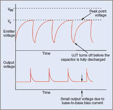
Figure 6 Relaxation oscillator waveforms
The amount of energy in the output trigger pulse is an important consideration in the triggering of thyristors. The energy in the trigger pulse produced by a UJT relaxation oscillator may be increased by increasing the value of the capacitor in the RC timing circuit. However, there is a practical limit to the current that the UJT can carry. If the capacitance is too high, the UJT might be damaged.
The UJT relaxation oscillator has two major disadvantages:
- The standoff ratio is fixed and can only be changed by changing the UJT itself. However, this will produce only limited changes.
- The UJT might not be able to deliver sufficient energy to trigger large, high current thyristors.
Unijunction Transistor (UJT) Key Takeaways
The Unijunction Transistor (UJT) and its relaxation oscillator circuit play a vital role in triggering thyristor power-control devices such as SCRs, triacs, and GTOs. These applications require precisely timed, fast-rise pulses to initiate conduction reliably, and the UJT’s unique characteristics make it well-suited for this purpose. Its ability to generate sharp, consistent trigger pulses using a simple RC timing circuit enables efficient control of power in various systems, including dimmers, motor speed controllers, and phase control circuits. Despite certain limitations like the fixed standoff ratio and limited current capacity, the UJT remains an essential and cost-effective component in the design of low- to medium-power triggering circuits.