In this article, we have covered Three-Phase Synchronous Motor construction, working principle, starting methods, and applications in details.
- Synchronous Motor Construction
- Operating Principle
- Applications of Synchronous Motors
- Starting Methods for Synchronous Motors
A three-phase synchronous motor has no starting torque. It has to be brought up to speed or as close to it as possible by some other means so that it can pull itself into synchronism.
Once up to speed, the rotor field can be excited with direct current and the rotor is, in effect, then dragged around at the same speed as the three-phase stator field. Its speed is synchronized with that of the stator field. This is markedly different in principle to the induction motor, where the rotating field of the stator is pushing against the induced rotor field. That causes the rotor to rotate, but with some slip, whereas in the synchronous motor there cannot be slip, merely a ‘hanging back’ due to the load imposed on the machine. This is illustrated in Figure 1 and shows as a torque angle. If the load becomes too great for a synchronous motor it immediately pulls out of synchronism and stops.
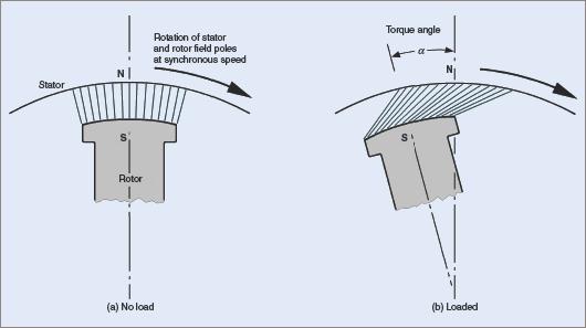
Figure 1 Relative position of stator and rotor magnetic fields
Synchronous Motor Construction
Stator
The stator has a three-phase winding and is of the same type as that in an alternator or induction motor.
When this winding is energized with AC it produces a magnetic flux that rotates at a speed called the synchronous speed. It is the same speed at which the synchronous machine would have to be driven to generate an AC voltage at line frequency.
The speed of the rotating magnetic field can be derived from the following formula:
$$ n=\frac{120f}{p}$$
Rotor
Although of similar construction to the alternator rotor, it is usually made with salient poles. When excited with DC it produces alternate north and south magnetic poles, which are attracted to those produced in the stator.
Operating Principle of Synchronous Motor
A synchronous motor works on the principle of magnetic attraction between two magnetic fields of opposite polarity; one is the rotating magnetic field of the stator and the other is the magnetic field of the rotor.
A synchronous motor has torque only at synchronous speed, so special steps have to be taken to get the motor up to speed and synchronized with the supply. The two magnetic fields are then rotating at the same speed and lock in with each other.
Effect of Load on a Synchronous Motor
When a synchronous motor runs on no load, the relative positions of stator and rotor poles coincide (see Figure 1(a)).
When a load is applied, the rotor must still continue to rotate at synchronous speed but owing to the retarding action of the load, the rotor pole lags behind the stator pole. Their relative positions are displaced by the angle a which is called the ‘torque’ or ‘load’ angle (see Figure 1(b)). The greater the load applied, the greater the torque angle.
The magnetic coupling between each stator and rotor pole distorts according to the load applied. If the load on the motor becomes excessive, the magnetic coupling breaks and the rotor slows down until it stops.
When the motor is rotating at synchronous speed, with a fixed DC excitation in the rotor windings, the rotor flux cuts the stator windings, inducing a voltage in each phase winding. By Lenz’s law, this voltage opposes the applied voltage. The phase relationship between this induced voltage and the applied voltage depends on the relative positions of each stator and rotor pole, which in turn depend on the load applied to the motor.
Using the example of an ideal synchronous motor with no losses, we can examine the operation on no load. Neglecting motor losses, on no load the torque angle is zero, and so the induced voltage Vg and the applied voltage V are equal and opposite. The resultant voltage VR across the windings is zero, and so the current drawn from the supply is also zero. This is illustrated by the phasors in Figure 2(a).
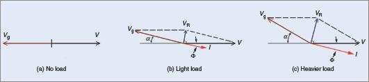
Figure 2 Effect of load on the line current with constant excitation
When a light load is applied to the motor, the torque angle α increases, and the induced voltage Vg in the stator windings is now (180 − α) °E out of phase with the applied voltage V (see Figure 2(b)).
These two voltages combine to produce an effective voltage VR across the stator windings, which is sufficient to draw a current I from the supply. Because of the relatively high inductance of the stator windings, the line current I in each winding lags each resultant voltage VR by nearly 90°E. This causes the line current I to lag the applied voltage by Φ.
As the load is increased, so the torque angle is increased. This causes an increase in the resultant voltage VR across each stator winding (see Figure 2(c)). Because of the increase in the value of VR, the line current I increases and the phase angle Φ between the applied voltage V and the line current I also increases. Therefore, for fixed excitation, any increase in the load on a synchronous motor will cause an increase in the line current, at a lower power factor.
Effect of Varying Field Excitation
If the load applied to a synchronous motor is constant, the power input to the motor is also constant. When the rotor field excitation is varied, the induced voltage in each stator winding is also altered.
The phasor diagram in Figure 3(a) overleaf represents the conditions for a given load at unity power factor. The power input per phase is VI1. If the rotor field excitation is decreased, the induced voltage Vg decreases (see Figure 3(b)). This causes the line current I2 to lag the applied voltage V by Φ2.
Since the load, and so the power input, is constant, the power component of I2 must remain the same as I1 in Figure 3(a). The line current I2 must increase to accommodate the lagging power factor. Therefore, a reduction in the DC field excitation causes an increase in line current and a lagging power factor.
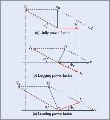
Figure 3 Effect of varying the DC excitation
If the DC excitation is increased, the induced voltage Vg increases (see Figure 3(c)). The line current I3 will therefore lead the applied voltage V by Φ3, and will also be greater than I1 in Figure 3(a) because the power component is the same, owing to the load remaining constant. Therefore, an increase in DC excitation causes an increase in line current, and a leading power factor.
It can be seen that if the excitation of a synchronous motor on a constant load is varied from a low to a higher value then:
1. The Stator Current Gradually Decreases, Reaches A Minimum, And Then Increases Again
2. The Power Factor, At First Lagging, Gradually Increases, Becomes Unity When The Stator Current Is A Minimum, And Then Decreases Again But Becomes Leading.
Care should be taken when adjusting the excitation of a synchronous motor. There are limits to which it can be taken with safety.
Over-excitation and under-excitation can cause the synchronous motor to become unstable. Once these limits have been exceeded, the power produced by the motor decreases and the danger of overloading becomes imminent as the machine exceeds its design limits.
The most obvious situation is one of under-excitation where the magnetic bond between the rotating field and the rotor is so weakened that the load exceeds the pull-out torque of the motor and it drops out of synchronism.
Over-excitation creates a situation where the line current and mechanical load exceed the full-load rating of the machine and the magnetic bond becomes so stiff that changes in load place undue mechanical stresses on the motor shaft.
Hunting in Synchronous Motors
A change in the load on a synchronous motor causes a change in the value of the torque angle (see Figure 1). In general, the inertia of the rotor prevents an instant change to the new conditions, with the result that the rotor shifts past the point of equilibrium and then has to correct itself.
While the rotor and the rotating field in the stator are still rotating at a synchronous average speed, the change in load on the rotor causes this periodic swing around the point of equilibrium. This surging or hunting causes an undesirable fluctuation in line current to the motor.
The usual method for damping these surges is to use a damper winding, called an amortisseur winding. It consists of copper bars embedded in the pole faces of the rotor and shorted out at each end (see Figure 4). Any surging causes an induced voltage in the copper bars. This results in a magnetic field being created and opposing the surging effect.
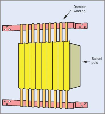
Figure 4 Salient pole with amortisseur windings
Often the shorting-out bars are extended around the rotor, resulting in a squirrel cage type rotor winding about the salient poles. While damping any tendency of the rotor to hunt, they can also assist the motor in starting by acting as sections of a squirrel cage winding. In effect this winding enables the motor to be started as an induction motor.
Applications of Synchronous Motors
Power Factor Correction
The characteristic of being able to adjust the power factor of a synchronous motor while it is running can be used to advantage in industry as a means of correcting the power factor of the loads supplied from the plant’s mains.
The synchronous motor can be run unloaded, but more often it is used to drive some item of equipment necessary for the operation of the plant; for example, air or hydraulic compressors, high-frequency alternators, large fans and blowers, or high-pressure water supplies.
An added advantage can be an economic incentive offered by distribution entities for ensuring a certain minimum value power factor in an installation. For example, the charge per kWh may be reduced if the power factor does not drop below 0.75 or some similar Figure. Where large amounts of power are being distributed and power factor correction is needed, specially designed synchronous motors are run without any load connected. Under these circumstances the over-excited synchronous motor is called a ‘synchronous capacitor’ or ‘condenser’.
Voltage Control
An important application is in the control of voltage for transmission lines. Synchronous motors are installed at suitable positions along the line and their excitation adjusted as desired, to cause them to draw lagging or leading currents in order to raise or lower the voltage. When synchronous motors are installed under these conditions there is greater stability of the voltage on the transmission line.
Low-Speed Drives
A synchronous motor has good efficiency and at low speeds its high initial cost is adequately compensated by the comparatively lower running cost. At low speeds the induction motor has a decreasing efficiency, while the synchronous motor retains its high efficiency.
Rock and Ore Crushing Heads
This application requires a crushing head that moves very slowly and has a very heavy rotating flywheel to provide kinetic energy as sudden shock loads are placed upon the crushing head.
Starting Methods for Synchronous Motor
Auxiliary motors
Some synchronous motors are equipped with a special motor designed for use only during the starting period. The auxiliary motor runs the synchronous motor up to speed, at which stage it is first synchronized and then connected to the supply. It is an expensive method, particularly if high starting torques are required.
Induction Motor Starting
In this method, a reduced line voltage is applied to the stator windings and the DC winding on the rotor is short-circuited. With the aid of the amortisseur windings, the complete machine behaves as an induction motor as it accelerates up to a speed slightly below synchronism.
At an appropriate time, the short is removed from the rotor winding, DC is applied to the rotor winding and the full line voltage applied to the stator winding. Because the speed is only slightly less than synchronous speed, the rotor field can lock in with the stator field and accelerate to synchronism.
Three-Phase Synchronous Motor Key Takeaways
Understanding the construction, operating principle, starting methods, and applications of three-phase synchronous motors is crucial due to their significant role in industrial and utility operations. These motors provide constant speed under varying loads, offer high efficiency, and enable power factor correction—making them ideal for critical applications like voltage regulation in transmission lines, low-speed heavy-duty drives, and improving plant power factor through synchronous condensers. Their unique ability to operate at synchronous speed and control reactive power makes them indispensable in systems where stable speed and electrical performance are essential.